
PROJECT DEVELOPMENT
I started out with make the main part, the flaps..
TEST 1
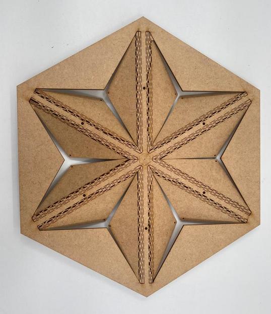
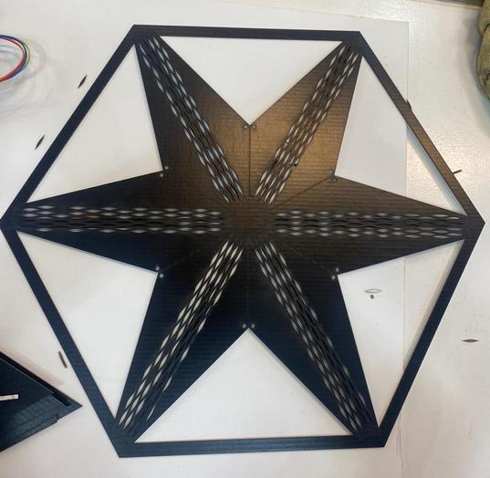
Instead of using metal or plastic hinges to connect the flaps, I made living hinges.
Material: MDF
3mm MDF turned out to be too thick for easy movement, so I used 1mm cardboard for the second test.
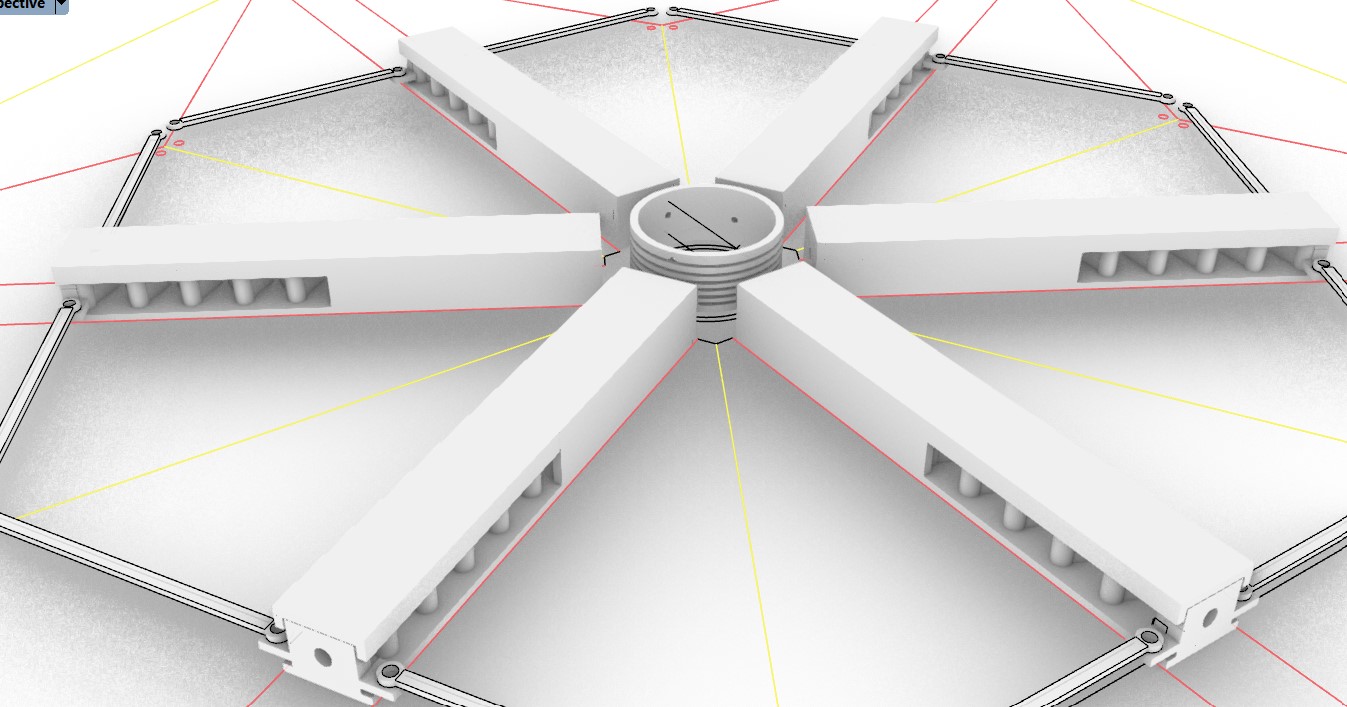
MECHANISM
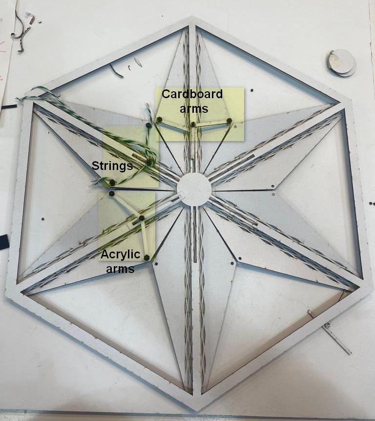
I designed arms for the movement of flaps and tested it out with different materials and thicknesses.
3d printing with PLA worked the best.
The next issue was with the flaps going back to its original position.
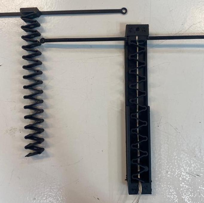
I decided to add a spring that would push the arms to its original position when the spring is released.
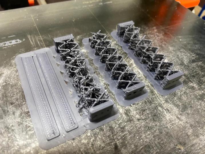
I tested the spring out with different materials, thicknesses and designs.
PLA in 1mm, 1.5 and 2mm thickness.
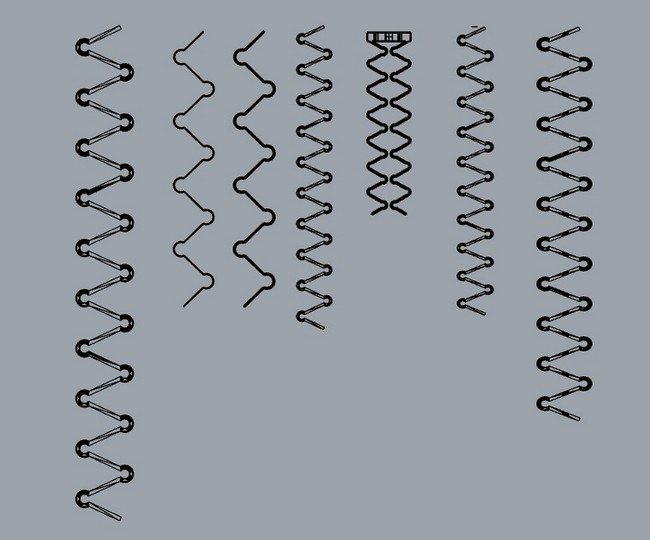
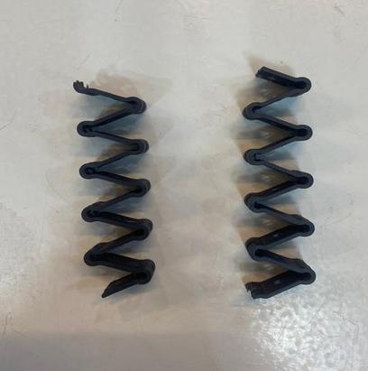
The prints in PLA turned out to be very brittle.
ASA in 1mm, 1.5 and 2mm thickness.
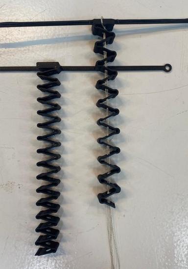
Testing a 2 spring system
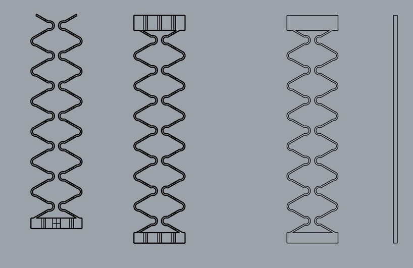
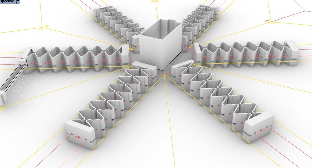
In theory, 2 springs mirrored and attached at the top and bottom should have kept it in line but that did not work.
So I needed to make housing to keep the spring in line.
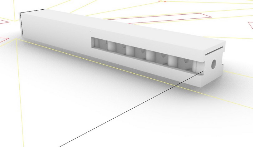
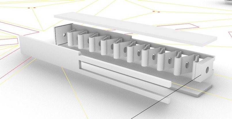
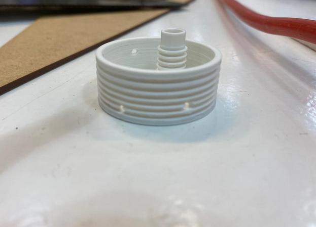
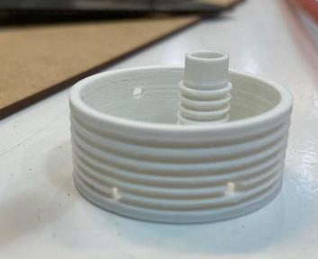
I also made a pulley in the center with holes that the string from each side can go through and get connected to the servo.
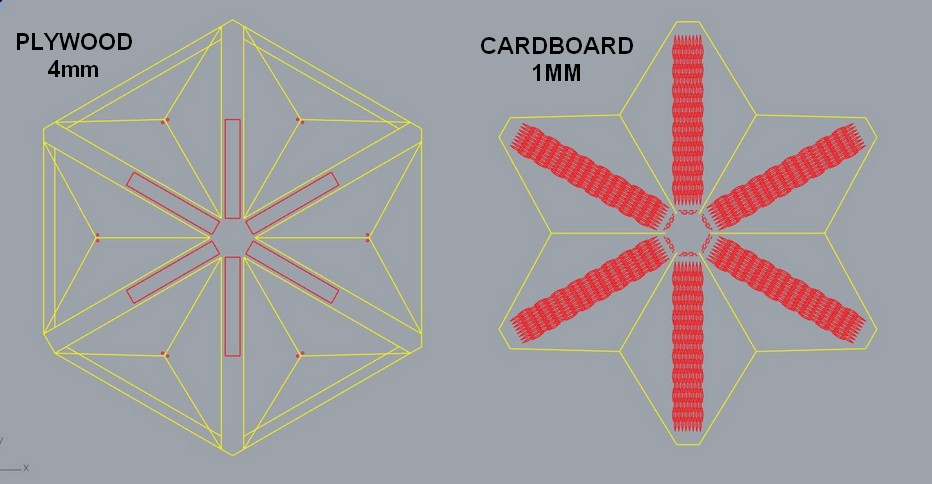
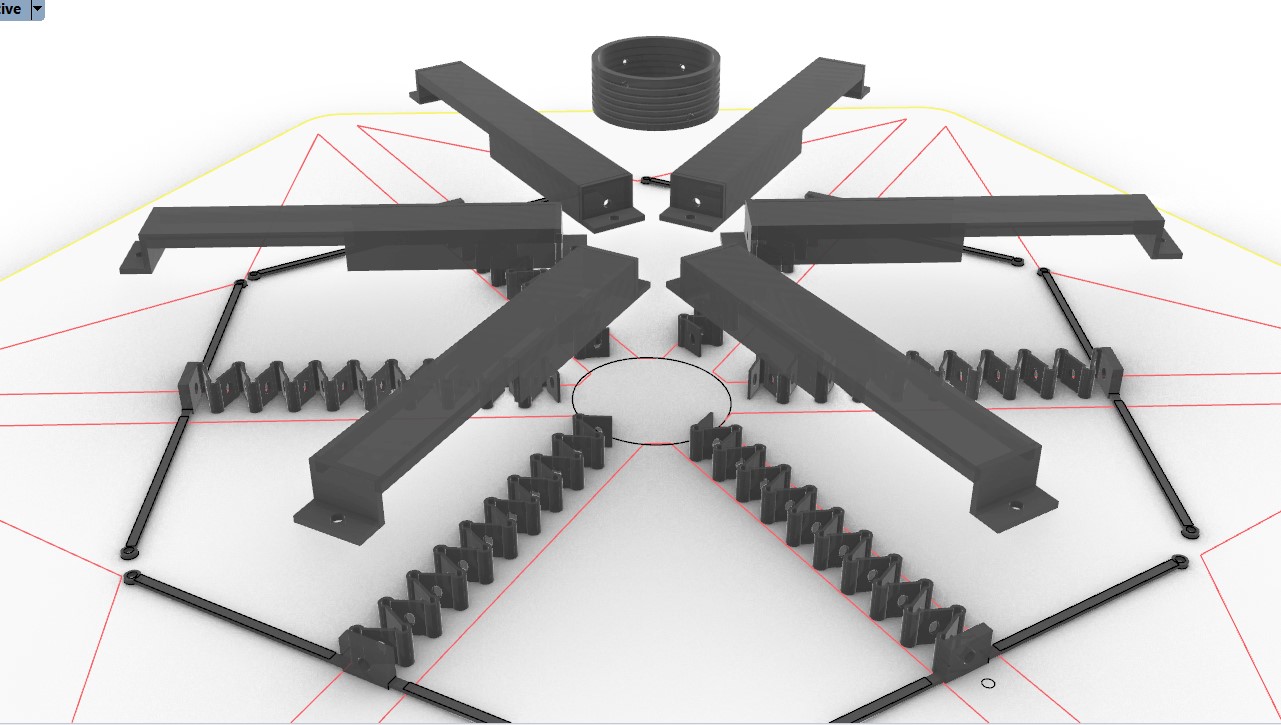
DESIGN FOR FINAL PROTOTYPE
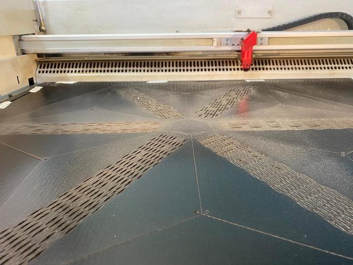
- LASER CUTTING
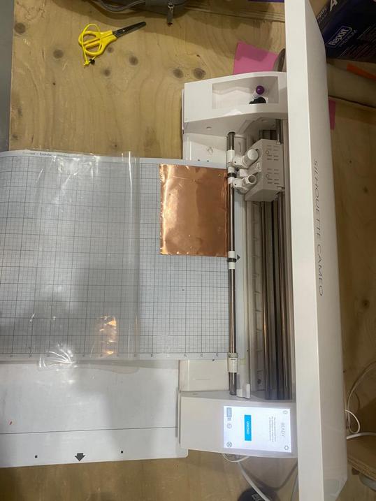
- VINYL CUTTING
- 3D PRINTING
- ELECTRONIC
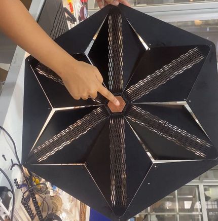
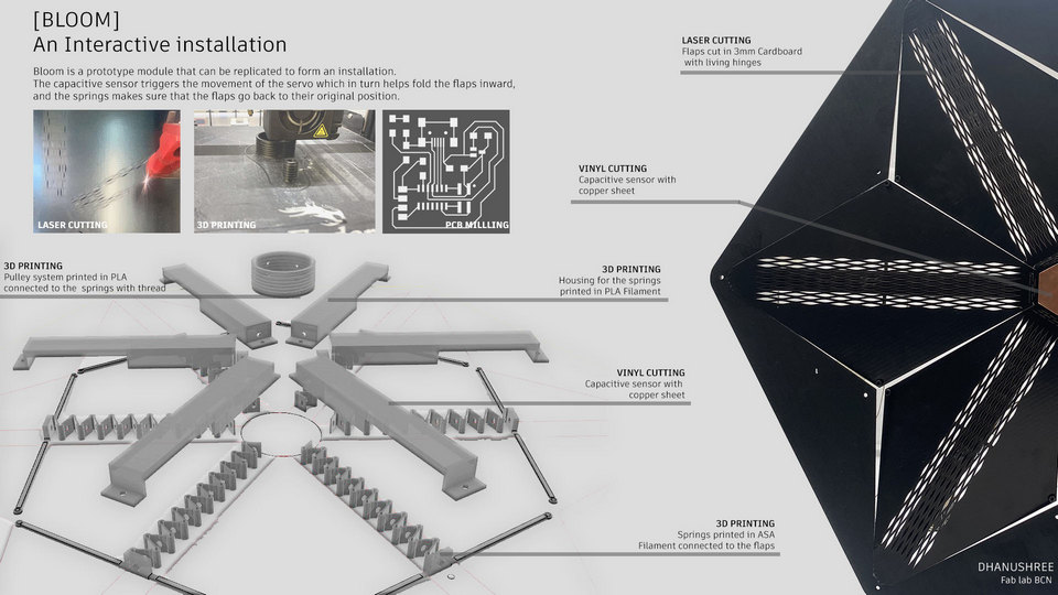
The flaps are laser cut in 1mm cardboard and the base in 4mm Plywood.
The input is a capacitive sensor cut from a copper sticker with a hole in the center to solder the wire in.
The Springs connected to the arms are printed in ASA, the housing in PLA and the central pulley also in PLA.
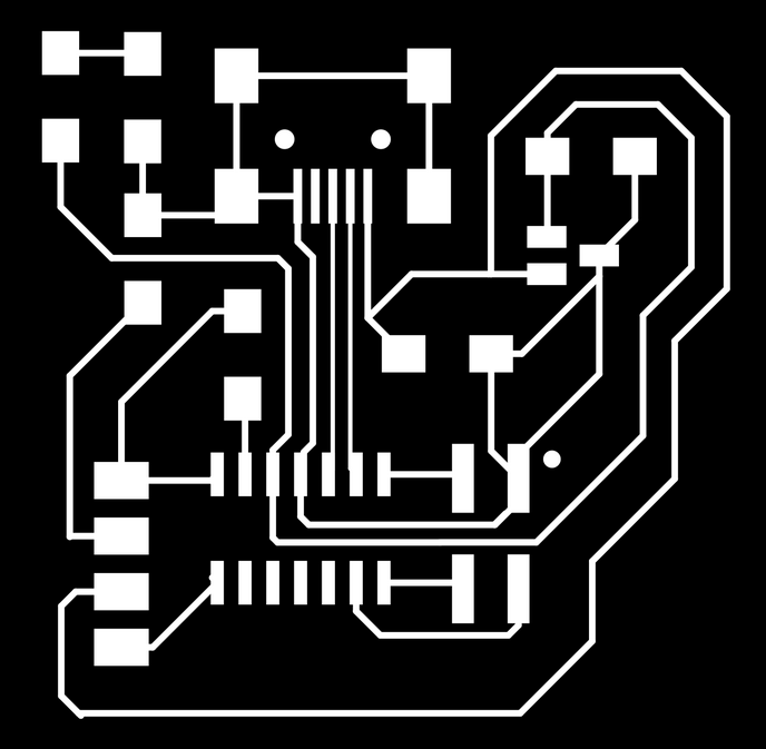
I need to make a PCB with would take input from a capacitive sensor and relay the signal to a servo motor.

ARDUINO CODE


ASSEMBLY
TESTING
I had to experiment with different
- ways of connected the string to the motor.
- Attaching the servo to the base with a laser cut plate/ spacers.
- Different thicknesses of the spring so there is less weight on the servo to pull.
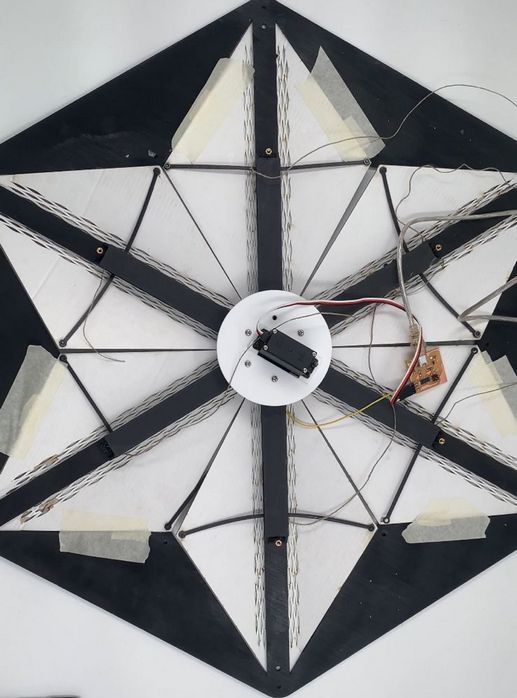
At first, I barely got any movement from the flaps because the springs I used were too thick and were putting a lot of pressure on the servo. So I printed out another set of spring with lesser wall thickness. I still don't have a full range of motion, but I have proof of concept now and I would like to fine tune the mechanism in further iterations.
Design files download
Rhino file
Laser cutting dxf
Stl for spring
Stl for pulley
Kicad
Arduino